



Custom Copper CNC Turning and Milling Parts
Overview
Copper connectors, terminals and adapters often combine rotational geometry with side holes, flats or slots, and these features must relate to a common assembly datum. XCM CNC combines turning and milling and evaluates datum transfer, hole locations and edge inspection against the drawing. The MOQ is 1 piece, with typical lead times of 10-15 days depending on complexity and quantity. Submit 2D/3D drawings, the copper grade and temper, critical tolerances and quantity for a quote.

Key Capabilities
- Materials: Copper grades specified by drawing, including oxygen-free copper when required
- Tolerance: +/-0.003 mm (+/-0.00012 inch), IT5 or IT6 accuracy, +/-0.01 mm shaft/bore fits; h6/H7 available
- Surface Finish: Ra 0.8 um on turned outside diameters; Ra 1.6 um finish-milled faces; Ra 3.2 um standard milled surfaces, as specified
- GD&T: 0.012 mm coaxiality for shaft/bore features and 0.015 mm position for hole groups; datum transfer and inspection by drawing
- Max Size: Turning up to diameter 1250 x 2000 mm; milling machine travel 3000 x 1600 x 1400 mm; combined-part size depends on geometry and setup
- Surface Treatment: Specify bare copper, required plating, or oxidation protection; confirm process availability and effects on contact faces and final dimensions
- Thread: Internal thread minimum M1.4; external thread minimum M2.0; standard, material suitability, effective depth, and inspection by drawing
- Precision Limit: +/-0.003 mm on suitable precision features or small critical dimensions; IT5 or IT6 available for suitable drawing-defined features and process routes
Copper Turned Datums for Milled Side Features
Turned outside diameters and end faces on copper connectors can serve as datums for subsequent milling of flats or side holes. Process planning checks the relationship between side features and rotational datums without assuming that every part can be completed in one setup.
Copper Cross-Hole Position from Rotary References
Cross-hole positions in copper terminals or adapters are evaluated relative to the turned axis or end face specified on the drawing. Hole-group position capability can reach 0.015 mm with suitable geometry and inspection conditions. The drawing defines the datum system.
Copper Deburring at Cross Holes and Slots
Intersections between milled slots or cross-holes and turned surfaces can retain burrs, so edge accessibility and acceptance criteria are reviewed before machining. Drawings and order requirements define the scope of internal deburring and cleaning.
Copper Contact Features Across Turning and Milling
Turning and milling can produce related contact faces, grooves, holes and flats on copper connectors according to drawing-defined functions. Copper conductivity can support material selection, while the grade, contact requirements and performance tests must be defined separately.
Specifications
| Product Name | Custom Copper CNC Turning and Milling Parts |
|---|---|
| Manufacturer | XCM CNC |
| Factory Location | Shenzhen, Guangdong, China |
| Quality System | ISO 9001, ISO 13485, IATF 16949, GJB9001C |
| Machining Process | CNC turning and milling |
| Material | Copper |
| Material Grade | Copper grade and temper specified by customer drawing; oxygen-free copper only when specified |
| Surface Treatment | Specify bare copper, required plating, or oxidation protection; confirm availability and effects on contact faces and final dimensions |
| Application | Connectors, terminals, or adapters with drawing-defined electrical or thermal function |
| Key Features | Turned axes and faces related to milled cross holes, flats, or slots as specified |
| Critical QC Requirements | Datum transfer, coaxiality, hole position, thread standard and effective depth, burr and cleaning requirements, specified finish, and inspection references |
| MOQ | 1 Piece |
| Typical Lead Time | 10-15 business days after drawing review |
| Drawing Formats | STEP, IGS, DWG, PDF, X_T |
Applications
Power Connection Terminals with Side Holes
Typical parts: Copper electrical terminal, side-entry terminal
Copper suits conductive connections. Combined turning and milling can first form the rotational terminal geometry, then produce side wiring holes and wrench flats. Hole positions, deburring and contact-face requirements are defined by the drawing.
Cable Connectors and Adapters
Typical parts: Copper cable connector, conductive adapter
Cylindrical mating sections can be turned, with cross-holes, slots or wrench flats added by milling. This suits parts combining a rotational datum with side features. Mating dimensions and electrical requirements are defined by the specified material and assembly drawing.
Sensor Mounting Fittings
Typical parts: Copper sensor fitting, sensor mounting body
These parts can combine turned outside diameters and end faces with milled mounting flats, side holes or locating slots to connect sensors to equipment interfaces. Specify sealing geometry, mounting dimensions and the working environment in drawings and operating requirements so the fitting arrangement can be established.
Electrode Holders for Welding Equipment
Typical parts: Welding electrode holder, copper electrode mount
Rotational mounting necks, end faces and transverse fixing holes often occur together in electrode holders. Combined turning and milling can relate these features in different directions. Conductive regions and mounting-location dimensions are defined by the copper grade and equipment drawings.
Conductive Slip-Ring Supports for Automation Equipment
Typical parts: Slip-ring mounting adapter, conductive connector body
Slip-ring interfaces often combine cylindrical locating sections with side lead-out holes or mounting flats, making combined turning and milling suitable. Specify mating datums, hole locations and the required conductive and electrical characteristics in the assembly drawing or order specification as the basis for machining and inspection.
Why Choose Us
Quality Systems and Inspection Equipment across Operations
The company operates under ISO 9001, ISO 13485, IATF 16949 and GJB9001C quality systems and uses equipment from DMG, Mazak, Matsuura and Brother. For copper connectors with side holes or flats, side-hole position can be checked using CMM measurement or other methods according to the drawing.
Turning and Milling Support from Connectors to Large Structural Parts
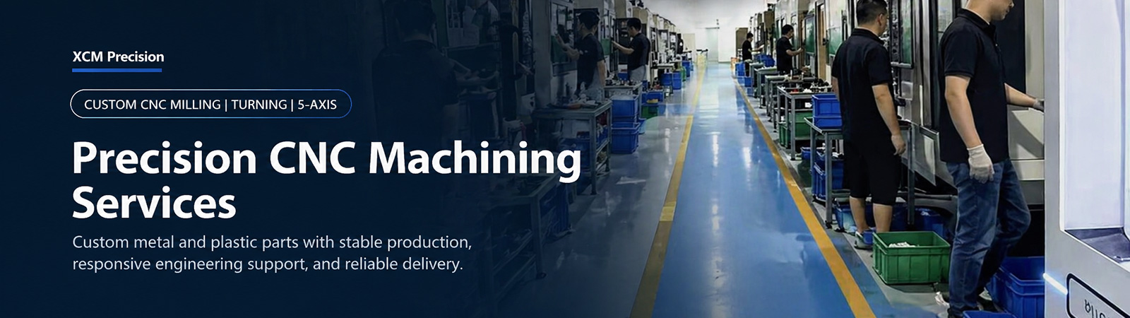
Factory equipment covers machining needs from small connectors to large structural parts. For copper parts combining rotational surfaces with side features, turning, milling and cross-hole edge inspection are planned against the drawing. Setup methods and machining limits depend on the individual part.
Equipment Matched to Operation Accuracy, Quality and Cost
Machines are selected from four equipment tiers from mainland China, Taiwan, Japan, and Europe and the United States according to part and operation accuracy. Selection for copper turned-milled parts considers rotational datums, side-hole positions and inspection requirements without assuming every feature can be completed in one setup.
Relating Side-Hole Positions to Rotational Datums
Identify axis or end-face datums, side-hole positions, cross-hole edge requirements and required reports on the drawing. These guide machining and inspection. Inspection results help verify whether features in different directions meet the assembly relationships.
Sample Approval before Batch Production
Samples can verify rotational geometry, side-hole positions and edge cleanliness requirements before approved parts proceed to production. An NDA can be signed as needed when connector or terminal drawings contain sensitive structural information.
FAQ
When is turning and milling useful for a copper part?
Combined turning and milling is worth evaluating when a part contains axial rotational surfaces along with side holes, flats or slots that must relate to a common assembly datum. The suitable process and setup plan depend on drawing geometry and inspection access.
Can all turned and milled features be completed in one setup?
Not necessarily. Single-setup completion depends on equipment, feature directions, fixtures and tool access. Operations and datum changes are evaluated against the drawing; one setup is not promised for every part.
How are side-hole positions related to a turned datum?
Define the rotational axis or end-face datum and specify side-hole position requirements on the drawing. These guide machining references and corresponding dimensional inspection. Hole-group position capability must be evaluated against spacing, geometry, fixturing and measurement methods.
How are burrs handled where a cross hole meets a copper surface?
Deburring and cleaning requirements for cross-hole exits, slot openings and internal edges can be reviewed against the drawing before quotation. Actual treatment depends on edge accessibility and acceptance criteria. Unspecified internal cleaning or testing should not be assumed to be included.
Which copper grade and surface protection should I specify?
Specify the grade and temper according to the connector’s conductive function, operating conditions and dimensional requirements, and state whether bare copper or surface protection is required. Plating scope and electrical performance cannot be inferred from the material name and depend on order requirements.
What files and details are needed for a quote?
Provide 2D/3D drawings, the material grade and temper, datums and tolerances for rotational and side features, quantity and intended use. STEP, IGES, STP, DWG or dimensioned PDF files can be used.
How long does a copper turn-mill prototype take?
Prototypes usually take 3-7 days. Actual timing depends on order requirements.
Request a CNC Machining Quote from XCM CNC
Send us your drawings. Our team will review the file and reply with a machining quote. MOQ: 1 piece, with competitive low-cost pricing.


