



Custom Precision Copper CNC Milled Parts
Overview
Copper contact blocks, mounting plates and heat-sink bases often combine mounting faces, hole patterns and pockets in one part. XCM CNC mills these features to drawings and plans dimensional inspection around assembly datums. The drawing specifies the copper grade and temper. The MOQ is 1 piece, with typical lead times of 10-15 days depending on part complexity and quantity. Submit 2D/3D drawings, material details and critical dimensions for a quote.

Key Capabilities
- Materials: Copper grades specified by drawing, including oxygen-free copper when required
- Tolerance: +/-0.003 mm (+/-0.00012 inch), IT5 or IT6 accuracy, +/-0.01 mm shaft/bore fits; h6/H7 available
- Surface Finish: Ra 1.6 um finish-milled faces; Ra 3.2 um standard milled surfaces; contact faces specified separately
- GD&T: 0.015 mm position for hole groups; 0.02 mm flatness at machining areas up to 1030 x 1030 mm; datums and inspection method by drawing
- Max Size: 3-axis milling travel 3000 x 1600 x 1400 mm; parts up to approximately 2600 mm long depending on fixturing and setup
- Surface Treatment: Bare copper, plating at 3-20 um film thickness, or polishing; film thickness is considered on contact faces and fits
- Thread: Internal threads from M1.4, external threads from M2.0; go/no-go or ring gauge inspection for functional threads
- Precision Limit: +/-0.003 mm on precision features and critical dimensions of parts under 100 mm; +/-0.05 mm on parts over 500 mm
Copper Milling for Flat Contact Faces
We mill mounting faces, contact faces and pocket floors on copper plates and blocks. Flatness capability is 0.02 mm over a maximum machining area of 1030 x 1030 mm, with finish-milled roughness of Ra 1.6 um. Precision features and critical dimensions on small parts under 100 mm can achieve +/-0.003 mm, while parts over 500 mm use +/-0.05 mm. Flatness of large, thin copper plates requires separate evaluation against thickness and clamping methods.
Copper Hole Patterns and Position Control
Hole patterns and locating holes are machined from drawing datums. Inspection datums must match assembly datums for results to reflect the assembled condition. Hole-group position capability is 0.015 mm, depending on hole diameter, spacing, count and inspection method. Locating and pin holes can be machined to H7/H8. Tapped holes start at M1.4, with functional threads checked using go/no-go or ring gauges.
Copper Pocket and Slot Milling with Burr Control
Pockets and slots on electrode blocks, contact parts and heat-sink bases have a minimum slot width of 0.3 mm. Deep slots require evaluation against depth and tool rigidity. End mills limit internal corner radii to a minimum of R0.5 mm. Sharp corners require EDM or a design adjustment. Copper is relatively soft and ductile, making cut edges prone to burrs. Standard sharp-edge treatment is a 0.1 mm edge break. State acceptance criteria on the drawing where contact faces or slot openings have stricter burr requirements.
Copper Thin Walls and Heat-Sink Fin Milling
Copper thin walls and fins can move during clamping or material removal. Minimum metal wall thickness is 0.5 mm, requiring blank pretreatment, stress-relief aging and optimized machining parameters. Minimum fin thickness is 0.8 mm with minimum spacing of 1.0 mm. For tall fins, or where dimensions must be maintained after surface treatment, distortion, burrs and coating-thickness changes need evaluation together.
Specifications
| Product Name | Custom Precision Copper CNC Milled Parts |
|---|---|
| Manufacturer | XCM CNC |
| Factory Location | Shenzhen, Guangdong, China |
| Quality System | ISO 9001, ISO 13485, IATF 16949, GJB9001C |
| Machining Process | CNC milling |
| Material | Copper |
| Material Grade | Copper grade and temper specified by customer drawing; oxygen-free copper only when specified |
| Precision Tolerance | +/-0.003 mm on precision features and critical dimensions of parts under 100 mm; +/-0.05 mm on parts over 500 mm |
| Surface Roughness | Ra 1.6 um finish-milled faces; Ra 3.2 um standard milled surfaces |
| Surface Treatment | Bare copper, plating at 3-20 um film thickness, or polishing; film thickness considered on contact faces and fits |
| Application | Busbar connector blocks, heat-sink bases, welding electrode holders, RF cavity housings, and electronic packaging baseplates |
| Key Features | Milled mounting and contact faces, hole patterns, pockets, slots, thin walls, and fins |
| Critical QC Requirements | Drawing datums, hole position, flatness, thread standard and effective depth, edge and burr acceptance, surface finish, plating thickness effect, and inspection scope |
| MOQ | 1 Piece |
| Typical Lead Time | 10-15 business days after drawing review |
| Drawing Formats | STEP, IGS, DWG, PDF, X_T |
Applications
Conductive Contact Blocks for Power Equipment
A busbar connector block and copper terminal carry current through contact faces and bolted connections. Contact-face flatness and roughness determine whether the parts mate, while bolt-hole positions determine alignment with the busbar. These are key milling and inspection priorities. The drawing specifies copper grade and electrical requirements.
Heat-Sink Baseplates and Mounting Bases
A heat sink baseplate and heat sink mounting base contact a heat-generating component on one side and have fins or heat-dissipation grooves on the other. Contact-face flatness affects heat transfer into the part. Tooling and distortion limit fin thickness and spacing. Copper thermal conductivity is the main reason for material selection, while actual thermal performance depends on material condition and design.
Electrode Holders for Welding Equipment
A welding electrode holder and electrode clamp block must conduct electricity and mount securely to the equipment. Mounting end faces and locating holes determine electrode alignment with the equipment. Copper grade and electrical specifications follow operating requirements and drawings.
Copper Cavities for High-Frequency Equipment
An RF cavity housing and shielding enclosure primarily comprise cavities, cover mating faces and connection holes. Tools limit deep-cavity internal radii; at a depth of 40 mm, the minimum internal radius is R1.0 mm. Cover mating-face flatness affects fit after assembly. RF performance depends on design, material grade and coating, while machined features are accepted against drawing dimensions.
Copper Baseplates for Electronic Packaging
A copper heat spreader plate and package mounting plate are typically thin, flat plates with shallow grooves and a mounting-hole pattern. These parts are sensitive to flatness. Distortion from clamping and material removal must be evaluated in advance. Where plating is required, coating thicknesses of 3-20 um must be included in final dimensions.
Why Choose Us
Quality Systems and Equipment Support
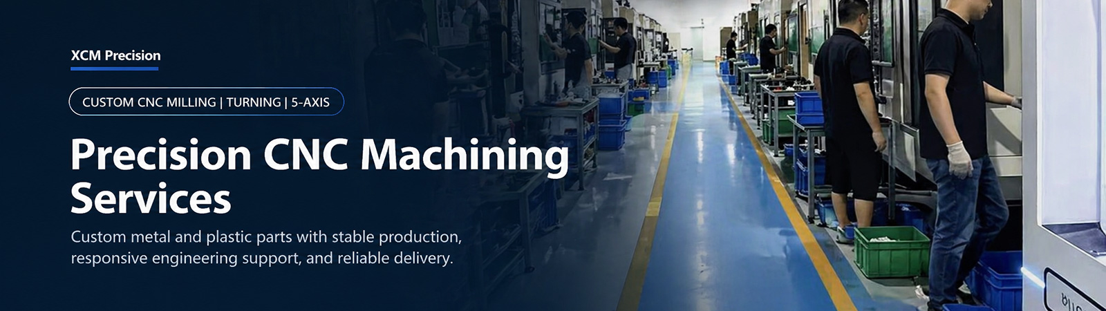
The factory holds ISO 9001, ISO 13485, IATF 16949 and GJB9001C certifications and uses machining equipment from DMG, Mazak, Matsuura and Brother. Milling and dimensional inspection of copper contact blocks, mounting plates and heat-sink bases are supported by these machines and quality systems.
Machining Coverage from Small Copper Contacts to Large Plates
The factory has equipment for small connector parts through large structural parts. Critical dimensions on small precision copper parts under 100 mm can achieve +/-0.003 mm. Three-axis milling travel is 3000 x 1600 x 1400 mm, supporting larger copper plates and busbars, with actual dimensions depending on clamping methods.
Equipment Matched to Accuracy and Cost Requirements
Our equipment spans four tiers from mainland China, Taiwan, Japan, and Europe and the United States. Machines are matched to the accuracy required by each part and operation. Copper contact faces, locating holes and general external geometry have different accuracy requirements, guiding machine selection to balance quality and cost.
Coating Thickness Considered Together with Mating Surfaces
Where copper contact faces require plating, coating thicknesses of 3-20 um change mating dimensions. During quotation, pre-plating or post-plating acceptance dimensions can be established together so finished dimensions meet assembly requirements. Cosmetic defect standards can also follow customer standards or approved samples.
Contact-Surface Packaging and Confidentiality
Copper contact surfaces are relatively soft and prone to impact marks and scratches. Parts ship in foam plus cartons or wooden cases according to the order. Shipping options include DHL, FedEx, UPS and sea freight. An NDA can be signed as required to protect drawings and project information.
FAQ
How do you control burrs in copper milled pockets and slots?
Edges are treated according to the drawing. Standard sharp-edge treatment is a 0.1 mm edge break. State acceptance criteria on the drawing where contact faces, slot openings or hole entries have stricter burr requirements. Copper is relatively soft and ductile. Internal edges in narrow, deep slots are harder to access, and treatment feasibility depends on width and depth.
How are hole position and mounting-face flatness inspected?
Hole locations and flatness are measured relative to drawing datums using a CMM or height gauge. CMM reports can be supplied when required, in the format specified by the order. Hole-group position capability is 0.015 mm and flatness capability is 0.02 mm over a maximum machining area of 1030 x 1030 mm. Feasibility depends on hole diameter, spacing, area, fixturing and measurement plans.
Does copper grade or temper change how the part is milled?
Yes. Softer copper conditions are more prone to tool adhesion and burrs, and temper affects thin-wall and fin distortion. Specify the grade and temper on the drawing. If omitted, we establish these with you before quotation rather than assuming pure copper or oxygen-free copper. State the acceptance basis for conductivity or thermal conductivity requirements. Material certificates can be supplied according to the order.
What details help assess thin copper fins or walls?
Thickness, height and spacing are most important, followed by surfaces that cannot be clamped or marked and flatness requirements. Higher height-to-width ratios increase distortion and chatter risks. Rib height-to-width capability is 8:1. Minimum fin and wall thicknesses are given in the capability descriptions above.
Does a finish-milled surface guarantee electrical contact performance?
No. Finish-milled roughness is Ra 1.6 um, but contact resistance also depends on copper grade, surface oxidation or coating, and contact conditions. Specify acceptance methods and scope separately where electrical testing or plating is required.
How large a copper plate can be milled?
Three-axis milling travel is 3000 x 1600 x 1400 mm, supporting large parts approximately 2600 mm long depending on clamping and fixing methods. Machine travel is not equivalent to workpiece size. Tolerance for parts over 500 mm is +/-0.05 mm. Flatness of large, thin plates requires evaluation against thickness and setup.
What information is needed for a copper milling quote?
Provide 2D/3D drawings, the copper grade and temper, tolerances, quantity and intended use. STEP, IGES, STP, DWG or dimensioned PDF files are accepted. A 3D model alone does not establish tolerances, datums or surface requirements. Include a dimensioned PDF or DWG as well.
How long does a copper milling prototype take?
Samples usually take 3-7 days. Production follows sample approval, with typical batch lead times of 10-15 days depending on part complexity and quantity. The MOQ is 1 piece.
Request a CNC Machining Quote from XCM CNC
Send us your drawings. Our team will review the file and reply with a machining quote. MOQ: 1 piece, with competitive low-cost pricing.


